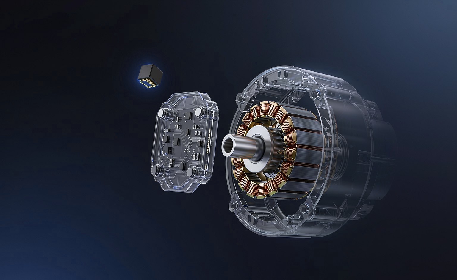
Scenario & Pain Points
A door lock actuator (central locking motor) needs to detect the latch Locked / unlocked position, the conventional approach places a Hall switch inside the actuator with a small local PCB for signal conditioning, then routes three or more wires (supply, ground, signal) back to the door control ECU. This structure has three pain points in cost and reliability:
- Local PCB cost— one small board per actuator means components, assembly and test all cost money;
- Harness cost— routing space at the door hinge is extremely tight; every extra wire raises both cable gauge and connector cost;
- Reliability— PCB solder joints and connector pins are common failure points over actuator lifetime; a door lock is a safety part, so field complaints are expensive.
Principle: 2-wire current output
The PCB-Less approach merges "supply" and "signal" onto the same pair of wires. The Hall IC changes its own operating current level— above the operate point (Bop) it outputs one current level, below the release point (Brp) it returns to another. A sense resistor in the ECU loop lets the voltage drop be read as the position signal:
The magnet moves with the latch; the Hall IC senses the field change and the ECU reads the current step to determine whether locking or unlocking is complete. The latching output keeps the signal stable while the magnet dwells — no chatter, no reset.
Recommended Parts & Parameters
Recommended for This Design SC25898 / SC25896 Automotive-grade 2-wire current-output latching Hall, parameters as follows (from product specification data):
| Parameters | SC25898 | SC25896 |
|---|---|---|
| Sensing Type | 1D Vertical Sensing | 1D Vertical Sensing |
| Operating Voltage | 4.0 ~ 24 V | 4.0 ~ 24 V |
| Operating Current | 4.1 mA | 6.0 mA |
| Output Type | Current Output (2-wire) | Current Output (2-wire) |
| Typical Bop / Brp | +80 / -80 Gs | +80 / -80 Gs |
| Package | SIP3 / TS2 | SIP3 / TS2 |
| Operating Temperature | -40 ~ 150°C | -40 ~ 150°C |
| Features | Factory programmed, integrated capacitor | Factory programmed, integrated capacitor |
The two parts differ in operating current level — selected to match different ECU sense resistors and detection thresholds. The symmetrical ±80 Gs switching points suit conventional latch magnet designs, giving reliable output transitions as poles alternate.
Application Notes
1. Factory programming ensures lot consistency
2-wire designs are sensitive to current-level accuracy. SC25898 / SC25896 are individually programmed at the factory to calibrate the current window, avoiding lot-to-lot drift that could cause ECU misjudgement — a key safeguard for volume production of automotive door locks.
2. Integrated capacitor simplifies external circuitry
An integrated capacitor suppresses coupled noise on the harness, further cutting external component count — consistent with the goal of “no PCB inside the actuator”.
3. Magnetic circuit matching advice
Choose the magnet so that when the latch reaches the sensing position the air-gap field Above +80 Gs (Bop), after leaving Below -80 Gs (|Brp|), with margin reserved across the full -40 to 150°C range for magnet temperature degradation. For air-gap calculation support, call us directly — we will help with the computation.
Solution Benefits
- Inside the actuatorEliminates the local PCB and assembly steps, directly cutting material and manufacturing cost;
- Harness reduced from 3+ wires to 2-wire, with hinge routing and connector cost falling in step;
- Fewer solder joints and pins means fewer failure modes, Reliability improvement;
- A current signal is highly immune to common-mode interference and stays stable over the long harness inside the door panel.
Further Reading
The same PCB-Less current-output architecture also applies toWindow lift, fuel flap and charge port actuatorsand other long-harness, space-constrained scenarios; the production library will add selection comparisons and application notes.